
제품 상세보기
;)
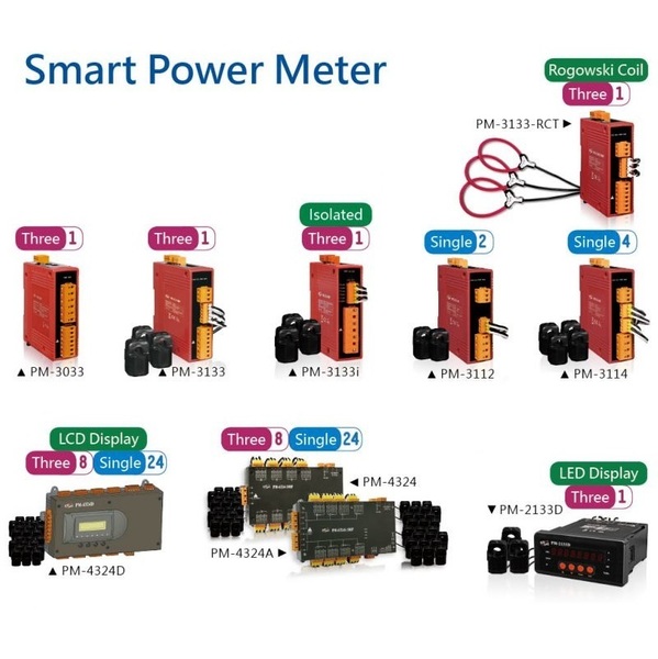
전력계 선택가이드
- 제품명
- 전력계 선택가이드
- 용도
- Smart Power Meter
- 특성
- 선택가이드
- 제조사
- ICPDAS (대만)
|
Single-phase/3 Phases/Multi-circuit Smart Power Meter
|
||||||||||
| Model | Phase | Loop | Bi-dir. Energy (Note 6) |
CT Included | Max. Voltage | Max. Current | Max. CT ID | Cable Length | ||
|---|---|---|---|---|---|---|---|---|---|---|
| RS-485 (Modbus/RTU) |
Ethernet (Modbus/TCP) |
CAN bus (CANopen) |
||||||||
| PM-3112-xxx | PM-3112-xxx-MTCP | PM-3112-xxx-CPS | Single | 2 | N/A | Yes | 300 V | 200 A | 24 mm | 1.8 m |
| PM-3114-xxx | PM-3114-xxx-MTCP | PM-3114-xxx-CPS | 4 | |||||||
| PM-2133D-xxxP (with LED Display) |
PM-2133D-xxxP-MTCP (with LED Display) |
- | Three | 1 | Yes | Yes | 500 V | 400 A | 36 mm | 4 m |
| PM-3033 | PM-3033-MTCP | PM-3033-CPS | Three | 1 | Yes | N/A | 500 V | 5 A | N/A | N/A |
| PM-3133-xxx | PM-3133-xxx-MTCP | PM-3133-xxx-CPS | Three | 1 | Yes | Yes | 500 V | 400 A | 36 mm | 1.8 m |
| PM-3133-xxxP | PM-3133-xxxP-MTCP | PM-3133-xxxP-CPS | 500 V | 4 m | ||||||
| PM-3133i-xxxP (Note 5) |
PM-3133i-xxxP-MTCP | PM-3133i-xxxP-CPS | 600 V | 4 m | ||||||
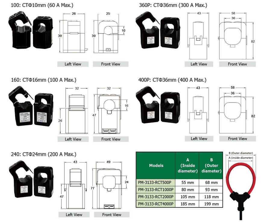
| PM-3133-RCTxxxxP | PM-3133-RCTxxxP-MTCP | PM-3133-RCTxxxP-CPS | Three | 1 | Yes | Yes | 500 V | 4000 A | 185 mm | 4 m |
| PM-4324-xxxP (1 main circuit) |
PM-4324-xxxP-MTCP (1 main circuit) |
PM-4324-xxxP-CPS (1 main circuit) |
Single/ Three |
24/8 (Note 4) |
Yes | Yes | 500 V | 400 A | 36 mm | 4 m |
| PM-4324A-xxxP (1 or 2 main circuit) |
PM-4324A-xxxP-MTCP (1 or 2 main circuit) |
PM-4324A-xxxP-CPS (1 or 2 main circuit) |
500 V | |||||||
| PM-4324D-xxxP (with LCD Display) |
PM-4324D-xxxP-MTCP (with LCD Display) |
PM-4324D-xxxP-CPS (with LCD Display) |
600 V | |||||||
| Note 1: Maximum CT cable length can be extend to 8 m. (except for Rogowski Coil CT), and the accuracy does not decrease. [We suggest to use twisted pair cable AWG18-14, sectional area from 0.75 ~ 2.0mm2.] Note 2: The end of power meters with -xxx or -xxxP means the specification of the CT. Users can choose the suitable one based on difference of current range and cable section area. Note 3: The end of power meters with -xxxP, the P means CT has built-in circuit protection to prevent CT from secondary open-circuit danger to human. Note 4: The PM-4324A has 2 separate main circuit inputs that can use in the different power system. Note 5: Built-in AC isolator protection, this means total isolation between the AC measurement side and the control side. Note 6: [Bi-dir. Engergy] stands for [Bi-directional Energy]. |
||||||||||
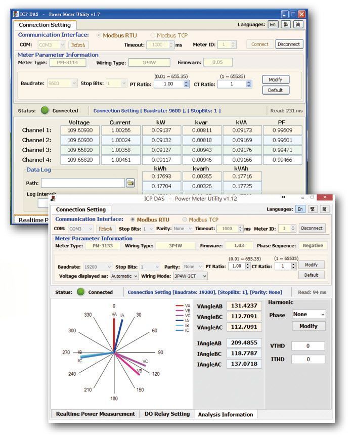
Power Meter Utility

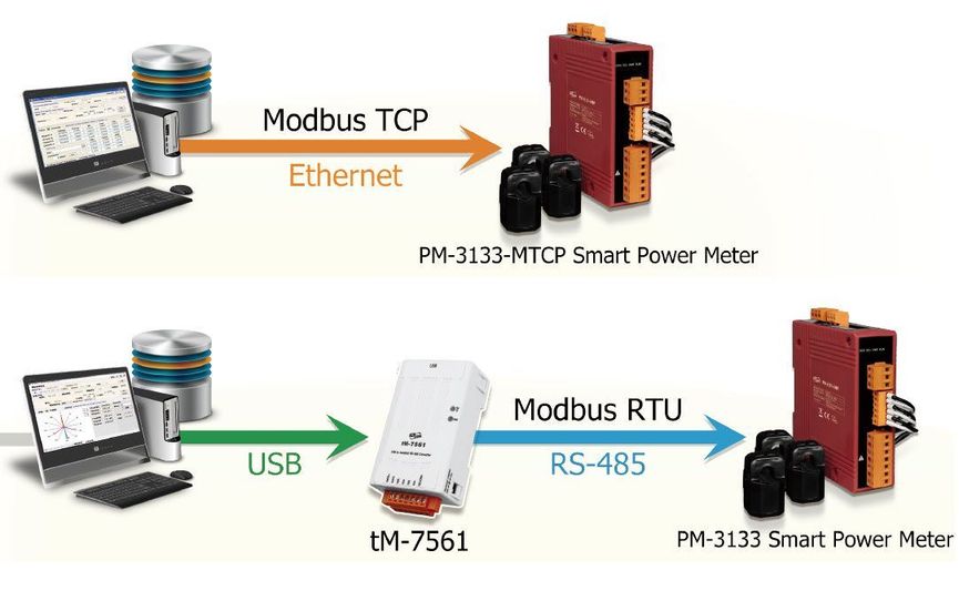
By Modbus RTU or Modbus TCP protocol, it enables to connect with ICP DAS Power Meters and data retrieving.
Real time monitor power measurement values of the meter.
Real time setting up parameters of the meter.
Restore the parameters of the meter to default settings.
Support Data Log function.
Power Meter Utility has to be installed on PC and it enables to retrieve and display the power measurement values that measured by power meter via COM Port or Ethernet. The users will be able to read the power measurement values and to perform parameter settings of the meter.
CANopen Master Utility
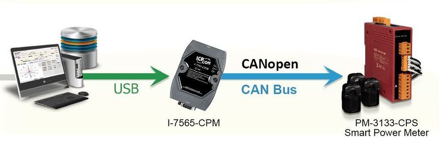
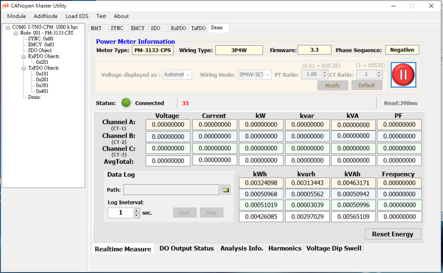
For CANopen master devices, ICP DAS provides a friendly CANopen master utility tool to help users to test and set CANopen slave devices easily. This utility tool can function as a simply CANopen master tool for controlling CANopen devices on the CANopen network. It provides several functions, such as NMT protocol, SYNC protocol, EMCY protocol, SDO protocol, PDO protocol, and so forth.
It features:
1. Auto-scan all the CANopen master that the CPMUtility has supported.
2. Auto-scan all the CANopen slave devices on the CANopen network.
3. Support EDS file.
4. Dynamic PDO object setting easily.
5. Node Guarding Event and Heartbeat Event detection.
6. EMCY message receiving.
7. Maximum 5 SYNC message producers per CANopen master.
8. Support I-8123W, I-87123, PISO-CPM100(U), I-7565-CPM and PISO-CAN/ PEX-CAN/PCM-CAN CPM Libraryfor version 2.00 later.
9. Support OS: WinCE5.0/CE6.0/XPe and Win2K/XP/Vista/732-bit system.
관련 상품
- 관련 상품이 없습니다.